|
EngMod2T Detailed Description |
![]()
![]()
![]()
![]()
![]()
|
|
Engine Layouts
The current version of the software can simulate engines ranging from 1 to 8 cylinders with the following layouts:
Two versions of scavenging / inlet systems are available:
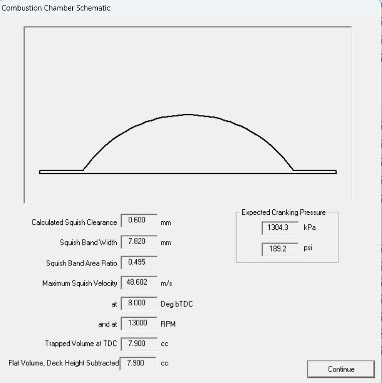
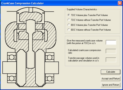
It has built in calculators for basic head shapes, crankcase compression ratio and target BMEP |
|
|
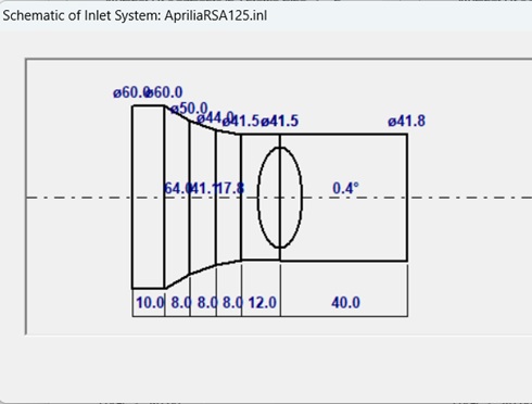
Types of Inlet Systems
The following is a brief summary of the available inlet systems:
|
|
|
Types of Inlet Ports
EngMod2T is one of the very few programs that model cylinder reed valves correctly with a combination of cylinder ports, Boyesen ports and floor ports.
|
|
|
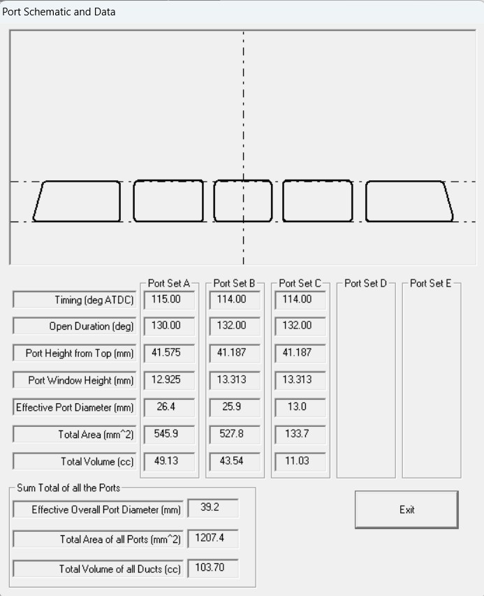
Scavenging Model
The scavenging model is based on the Blair model with some refinements. It is based on measurements in a special type of test apparatus. Transfer Ports The software can model from 2 to 12 ports
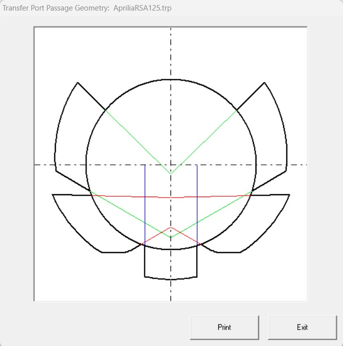
There is also an option to model the geometry of the
transfer port ducts into the cylinder
|
|
|
Combustion Modeling
Two types of combustion modeling is available and both are based on the typical two-zone model (a burnt and an unburnt zone):
|
|
|
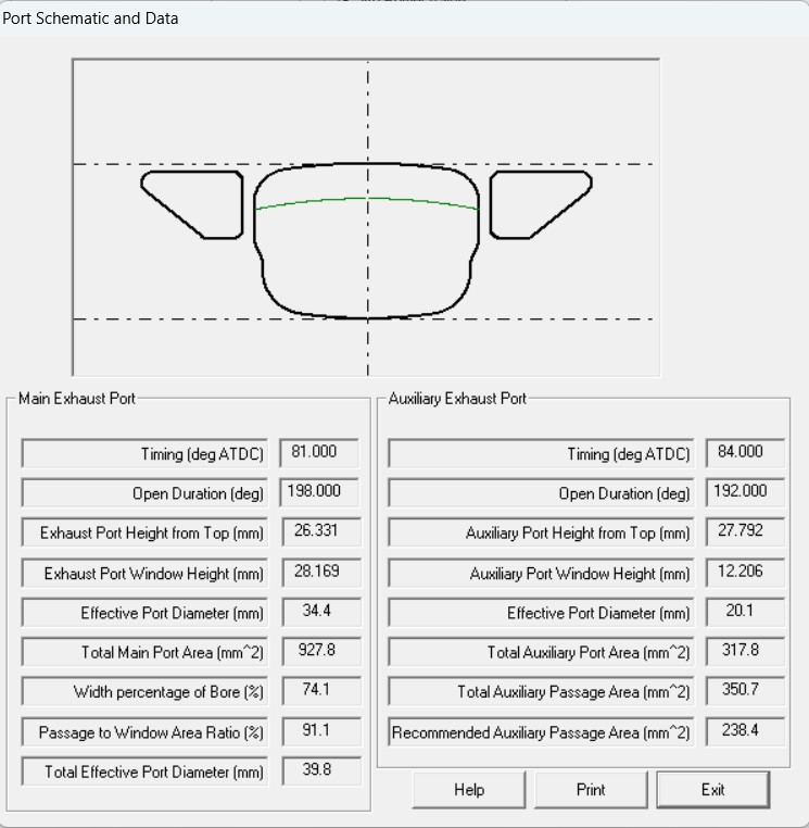
Exhaust Ports
The exhaust ports fall into four main classes:
The first two types also has the option of having a powervalve. The powervalve can be of the governor type (mechanical or servo motor) or of the pneumatic type. It can be in the main port only or also in the auxiliary ports. The auxiliary port powervalve can be controlled by the main powervalve or separately. |
|
|
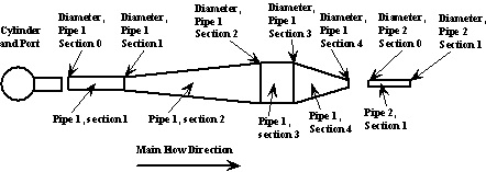
Exhaust Systems
The available exhaust systems fall into three main classes:
Each class can be further divided into the following types:
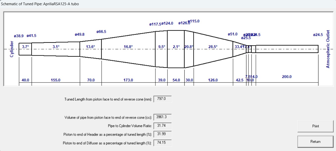
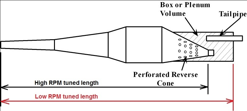
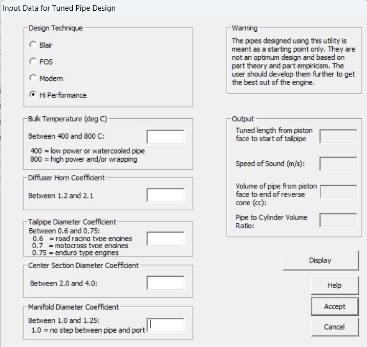
The pipes can also be fitted with a controlled resonating chamber commonly know as an ATAC system. There is also a utility that can generate a tuned pipe based on one of the following 4 models:
|
|
|
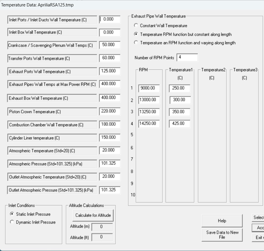
Wall and Atmosheric Temperature and Atmospheric Pressure
The wall temperature for each duct, plenum, cylinder, head, bore, piston crown, crankcase or box is entered. The exhaust system wall temperature can be entered as a single value or as a function of engine RPM and / or of pipe position. The atmospheric temperature and pressure for the inlet and exhaust can be separaely entered. |
|
|
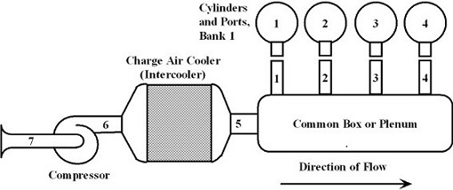
Supercharger Modeling The current release allows for the modeling of a single supercharger with or without Charge air cooler (intercooler). Software is included to digitize the compressor characteristics. It can be either a centrifugal compressor or twin rotor type compressor (eg Roots).
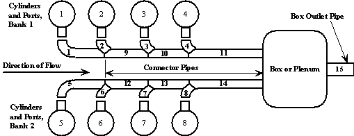
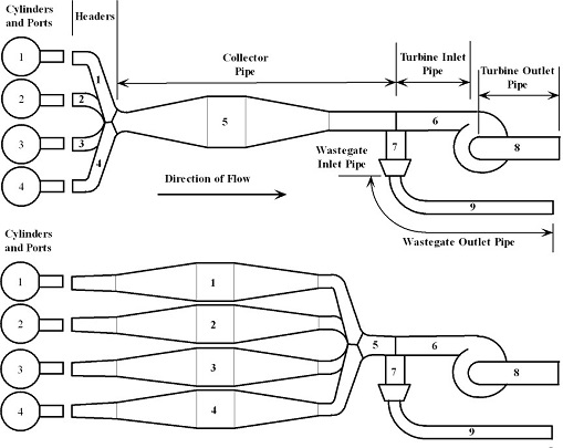
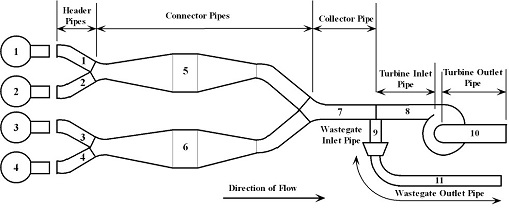
Turbocharger Modeling The current release allows for the modeling of a single turbocharger with or without Charge air cooler (intercooler) and wastegate. Software is included to digitize the compressor and turbine characteristics. The exhaust system can be modelled as straight pipes or tuned pipes. The figure shows three of the tuned pipe options available for an I4 engine. |
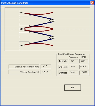
Some of the Tools included in the modeller Dat2T:
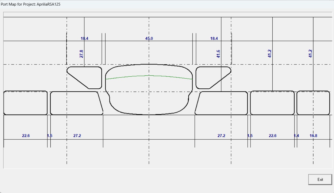
As part of the pre-processor, Dat2T, there is a utility to verify the port window design but it requires the scavenging port model as input:
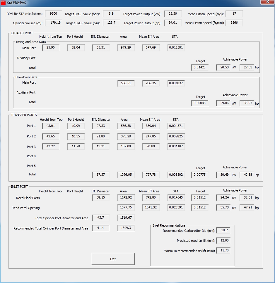
Also part of the pre-processor, Dat2T, there is a utility to verify the Specific Time Area (STA) design:
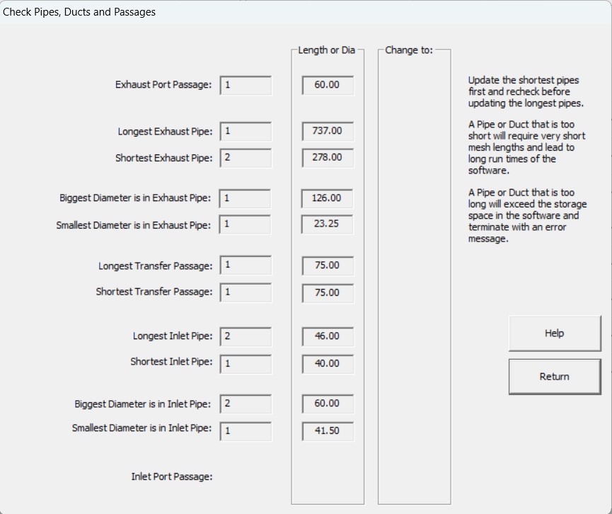
There is also a utility to verify the Pipe, Port and Duct design:
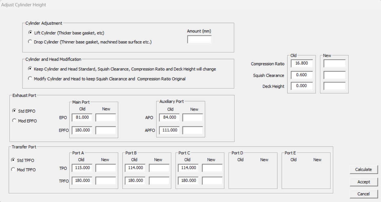
And it also has a utility to update the port timing by lifting or lowering the complete cylinder:
Example of the turbocharger maps in the graphing utility Post2T:
To use a compressor map as part of the simulation it has to be extrapolated into the surge region and to the negative (reverse) flow region. The following is an example of such a digitized and extrapolated map:

To use a turbine map as part of the simulation it has to be digitized. As it is very difficult to obtain a full turbine map, the software currently uses an approximation known as the "swallowing curve". The following is an example of such a digitized swallowing curve:

![]()
![]()
![]()
![]()
![]()
Copyright © Vannik Developments. All rights reserved.